|
In this section you will learn how to make a wheel, you will need 3D
Studio max 5 and the official RA2 exporter from the ra.com site. This is
only one way to do it, but it works for me, and others. Note: you can
follow this tutorial in max 4.?, only the rendering to texture and uvw
mapping are different, use the tutorial files with max to learn how to do
this.
Part 1: Setting up
Cut and paste the text below into textfile and save it in your RA2
component directory as carwheel.txt
name = Car
Wheel
dir = carwheel
type = mobility
base = Wheel
model
= carwheel.gmf
preview = carwheel_preview.bmp
description =
Wheel made for tutorial.
passthru = wheel
contact =
wheel_traction
resistance = .2
grip = 2
damagesounds =
sounds\rubber_collision.wav,sounds\rubber_collision2.wav
attachsound
= sounds\cmp_wheels.wav
standard = 1
sort =
-10 |
Also in the components directory create a folder called carwheel, and
a subfolder called maps. Now you are ready to start max.
|
Before you start, open the 'Customise' menu in max and change
the units setup to be in meters, this helps in scaling your parts
to fit in the game.
In max create a torus by following steps 1-3 then dragging in
the left had viewport, then click on the modify tab (4) ready to
change its shape and size.
|
 |
|
| Copy the parameters in the
rollout from the right, paying attention to the smoothing
settings, you should get somthing similar in your prerspective
viewport. This mesh is going to be the wheels tyre, so it needs to
be wider. With the mesh selected right click in the viewport and
from the bottom menu choose convert to editable mesh |
 |
|
|
|
|
|
|
|
|
|
|
|
|
|
| Now to make the tyre wider, in
the modifier panel expand the rollout and select vertex, all the
vertices of the mesh should now be visible as blue dots. Click and
drag to select all the vertices on one side of the wheel, click on
the move button at the top, then the Absolute Mode button at the
bottom. Use the up and down arrows next to the x axis setting to
make the tyre wider, about 10 clicks does it. |
|
|
|
|
|
|
|
|
|
|
 |
|
|
Now to make the rubber effect. Open the material editor ,  , and
select any of the materials by clicking on the preview spheres in
the top window, then rename it to tyre. In the 'Blinn Basic
Parameters' rollout there is a small button to the right of the
diffuse colour, click it to get a new window, in this window
double click 'Noise'. Now change the noise parameters to match the
picture, and click the show in viewport button. Back in the main
window, select the mesh, then hit the apply to mesh button in the
material editor. , and
select any of the materials by clicking on the preview spheres in
the top window, then rename it to tyre. In the 'Blinn Basic
Parameters' rollout there is a small button to the right of the
diffuse colour, click it to get a new window, in this window
double click 'Noise'. Now change the noise parameters to match the
picture, and click the show in viewport button. Back in the main
window, select the mesh, then hit the apply to mesh button in the
material editor.
|
 |
|
| |
|
|
|
|
|
|
|
|
|
|
|
|
|
|
|
|
| Now you need to add a uvw
mapping modifier to the mesh. With the mes still selected click on
'Modifier List', scroll down and select 'UVW Mapping'. Change the
parameters to cylindrical and check 'Cap', you should get
something like on the right. |
 |
|
|
The tyre looks nice (well maybe it doesn't) but RA2 cannot
recognise the 'noise ' material type. You have to 'bake' the
texture, or 'render to texture', to make a bmp file that RA can
use to map onto the tyre. In the moifier stack, right click on the
UVW Mapping and select 'collapse to'.
Move the tyre mesh so it is at 0,0,0 in the scene by clicking on the move tab,
turning off the Absolute mode at the bottom, then typing 0.0 into
all the x y and z box at the bottom.
|
|
| |
|
|
|
|
|
|
 |
|
| From the main menus across the
top select Rendring>>Render to texture. In the general
settings rollout set a path for the file to be saved to, close the
rollout, and open the Selected Object settings. Click on Add...,
then complete map, then add elements. Change the filename of the
bmp that will be generated to something more suitable, and click
render. Now you can see the bmp file that has been saved, close
this and the reder to texture dialog. A new modifier has been
added to the stack for the tyre now, Automatic flatten UVs,
collapse this modifer too. |
|
|
Re-open the materials editor, and click the same button you did
before to add the noise material, that now has an M in it. Click
the Noise button on the right just below the viewing spheres,
doulble click bitmap in the new window, then select the bmp you
just rendered. Go back to the modifier stack for the tyre and add
the Unwrap UVW. From the menus at the top of the uvw editor screen
select Mapping>>flatten mapping, and ok the dialogue box
that appears. You now see the tyre split into sections and laid
onto the map. Close the editor.
|
 |
|
|
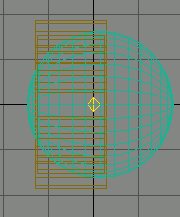
Now to make the rim of the wheel, create in the left viewport a
cylinder that is bigger in diameter than the inner part of the
tyre but smaller than the outside, convert to editable mesh and
move the vertices to make it the right proportions to fit the
tyre. Also create a sphere about 0.4 in radius and convert this to
ediable mesh also. Make sure all three meshes are at 0,0,0 then
line them up like the picture on the right. In the Perspective
viewport it should look like the rim, and then hubcap
(sphere). |
  |
|
| |
|
|
|
|
|
|
|
|
|
|
|
|
|
|
| In the spheres modifier turn
on the polygon selection tool, click and drag to highlight all the
polys that do not make up the hubcap, hit delete and ok the dialog
that pops up. |
 |
|
| Further down the modifier rollout under
the edit geometry section there is the attach button, click it and
then on the rim in the viewport, the part of the sphere left is
now part of the same mesh as the rim. Click on attach again to
turn it off. |
 |
|
|
Re-open the material editor and click on a blank sphere, this
is going to be the material for the rim. Change the colour of the
ambient and diffuse to 225,225,225, set the specular level to 55,
glossiness to 20, apply to the rim mesh and render to texture as
before for the tyre. When you go back to the material editor to
add the bmp, be sure to set the specular and glossiness back to 0
and 10 respectively. Move the perspective viewport around to give
a good view of the wheel, select rendering>> enviroment from
the main top menus, chage the background colour to something more
suitable, then close and select rendering>>render. Set the
size to 96x72, hit render, save this bmp as carwheel_preview in
the carwheel folder.
|
 |
|
The display part of the wheel
is finished. You now need to create the wheel the game will use to
detect collision with the ground and other objects. Create a
cylinder in the left viewport a touch smaller than the tyre.
Convert to editable mesh again and move the vertices around to
make it the right height etc. Rename it in the box at the top
right to be called 'wheel'. Right click in a viewport and select
properties, select the user defined tag and paste in the following
text:
Mass = 18.000000
Friction =
0.900000
Disable_Collisions = 0
Ellasticity =
0.700000
Optimization_Level = 0.500000
Unyielding =
0
Simulation_Geometry = 2
Proxy_Geometry =
<None>
Use_Display_Proxy = 1
Inactive =
0
Display_Proxy =
wheel_display | |
 |
| |
|
|
|
|
|
|
|
|
|
|
| |
|
|
|
|
|
|
|
|
|
|
|
|
|
|
|
|
Close the prefs window and
create another cylinder, with only 6 sides and larger than the
tyre in diameter, but thinner. Move to 0,0,0. Rename to
'wheel_traction' and add this into the user prefs:
Mass =
2.000000
Ellasticity = 0.400000
Friction =
0.300000
Optimization_Level = 0.500000
Unyielding =
0
Simulation_Geometry = 2
Proxy_Geometry =
<None>
Disable_Collisions = 1
Inactive =
0
Display_Proxy = <None>
Use_Display_Proxy =
1 | |
 |
|
|
|
|
 |
|
| For wheels to work propery in
the game, they have to be made facing downward in max, so to start
with make sure all the meshes are at 0,0,0 in the scene. Use the
hierarchy tab and turn on 'Affect Pivot Only', you are now free to
move the meshes pivot points as you wish without movine the meshes
themselves.Turn off the affect pivot only button, select all the
meshes, and rotate them through 90 degrees so they point down,
then hit the 'reset transform' button lower in the heirarchy
rollout. |
|
|
Now to add an attachment
point for the wheel, copy the setting from the pic on the right,
and place a point on the center of the top viewport. In the left
viewport move the point so it is at the edge of the tyre, then use
the rotate to to make the z axis of the point, point away fron the
wheel. Open the points user prefs and add
Type =
Attach
Attach = Axle_F
ID =
1 |
Finally delete all the omni lights. |
|
|
 |
|
|
Now you have to group the objects together and assign them to a
rbcollection.First select the tyre and rim, then choose from the
main menus Group>>Group, when the dilogue appears call the
group 'wheel_display', move back to the heirarchy rollout to move
the groups pivot point to 0,0,0. Repeat this step for the wheel
and wheel_traction meshes, only this time calling the group
'wheel_rbodies'. |
|
|
Goto the create rollout again, pick helpers from the icons
across the top, then reactor from the drop down selector. Click on
the RB Collection button and click anywhere in a viewport to
create one. Right click a couple of times to turn of the create
function, select the new rbcollection and open its modifier stack,
look for add button, then double click on wheel_rbodies group in
the diologue box.
Save the scene at this point, then run the gabriel exporter and
export the file to the carwheel folder as carwheel.gmf. Be sure to
check the preferences first, you should be exporting as binary, in
meters, and copying textures to \maps.
Go test and have fun. |
 |
 |
|
|
|
|
|
|
|
| |
|
|
|
|
|
|
|
|
|
|
|
|
|
|
| |